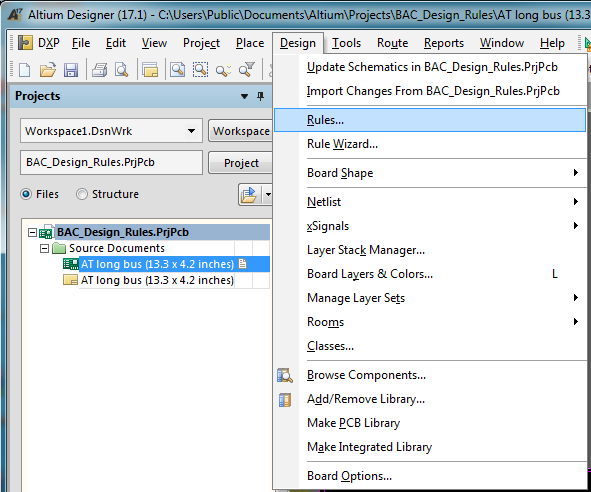
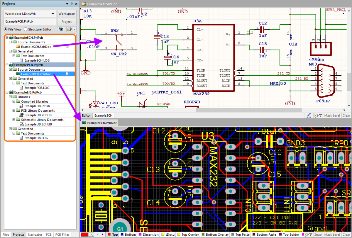
To create Gerber files from your.PCB file, open the.PCB in ARES, go to the OUTPUT menu (Next to File Menu), and click on Gerber/Excellion Output. That should then generate the gerbers for you. You have options on which layers you want to export (for example, if it is a 2 layer board, you only need top/bottom copper, Proteus will see that. The Import Wizard handles both Allegro PCB Design files (.brd) and Allegro ASCII Extract files (.alg). If you have Allegro PCB Editor versions 15.2 or 16 installed, you can directly translate Allegro PCB Design files (.brd) into Altium Designer PCB files (.PcbDoc) I thought it might be possible to convert the.brd file to the.PcbDoc with.

Altium Pcb Viewer
- The file extension for NC Drill data created in the Altium Designer PCB Editor is.txt. Click to open the Browse For Folder dialog and navigate to the CAM Imports & Exports folder you extracted from the download ZIP mentioned at the start of this article, and click OK.
- The Gerber format, RS-274-D, for printed circuit board specification was originally introduced in 1980. Since, there have been two major revisions, X1 and X2. The currently used formats are open ASCII formats for 2-D binary images and serve as the unofficial industry standard for PCB design files.

Our project is now complete. The schematic is drawn, the list of components is complete and verified, the PCB is composed and has been checked for errors, and the assembly drawing is ready. The next step is to upload all the required files in order for the PCB manufacturer and assembler to get the final (and already working) device. At the very least, the manufacturer should get information about the PCB materials and layers set, NCDrill files, and Gerber or OBD++ files to create a conductive pattern on the layers of the designed PCB. These files can be uploaded individually, but it is much easier and faster to use the OutJob file to output all the necessary files at once. Each output is configured with its own settings output format. OutJobs are very flexible – they can include as many or as few outputs as required and any number of OutJobs can be included in a project. The best approach is to use one OutJob to configure all outputs required for each specific type of output being generated from the project. Let’s create the OutJob file for exporting all output files of our drone PCB.
Make sure that project Kame_FMU.PrjPCB is active. Select File > New > Output Job File from the main menus to create a new OutJob file related to the project. A new OutJob editor will open in the design space with the settings of output files. In this editor, you can specify all the necessary documents for export and upload them at the same time. Simultaneously, the new.OutJob document will appear in the project tree.
The main section of this editor is Outputs and it is divided into groups depending on the type of documentation: Assembly, Fabrication, Report, etc. To manufacture and assemble the drone PCB, we need to get the following set of files:
- Schematic Drawing
- Assembly Drawing
- Pick and Place file for automatic component placement
- Bill of Materials report
- Board Stackup Information
- Gerber/ODB++ files to replicate the conductive copper pattern on a real PCB
- NC Drill files for PCB drilling
- 3D model of our PCB
How To Open Protel Pcb File In Altium
Once the OutJob file is configured, all these files can be uploaded with a few mouse clicks even after changes in the project. Also, the number of OutJob files in the project is unlimited, so in your projects, you can separate them by functionality outputs or by PCB variants. In the following guides, all the necessary documents and files will be configured and generated depending on their type